An Automation Tester That Never Gets Tired: Software Meets Hardware
An unfinished experiment with a camera, Raspberry Pi, Arduino, and XY plotter, and what must be verified first, including coordinate mapping assumptions, calibration, and completion feedback.
When a service has several payment methods, every deployment requires checking all of them from order to payment completion. Each provider encrypts its virtual keypad and shuffles the digits, and protected screen areas appear black in ordinary captures. This article is an interim record of an experiment that went outside software to reduce that repetition. The hardware was assembled; the software integration was not finished. What follows is what I would verify first if rebuilding it.
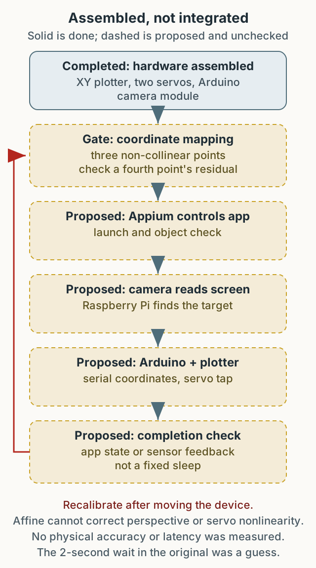
Figure 1. Solid is what was assembled; dashed is proposed. Coordinate mapping and completion feedback remained design only and were not verified on a real device.
Why hardware
The test framework also consumed a lot of CPU and memory. The machine at the time used a 3GHz 8-core Intel Xeon E5 with 64GB of memory, and monitoring showed CPU above 90% with swap usage reaching 200GB. Those are observations on that environment, not a benchmark for the same tests elsewhere. I considered moving some work to separate hardware coordinated through an API.
Mobile automation usually finds elements through the accessibility tree or screen capture. On heavily protected screens, such as payment flows, the capture may be empty or the virtual keypad layout may change on every visit. So the idea shifted from reading the screen to reproducing a physical press.
The proposed flow
The setup used an off-the-shelf XY plotter from AliExpress, with an Arduino and room for customization, plus a camera module connected to an Arduino or Raspberry Pi. The intended flow was:
- Appium launches the app and checks whether an object exists.
- The camera captures the screen and identifies the object.
- The coordinates are sent over serial to the Arduino.
- Two servos move the X and Y axes to press the target.
- Appium or the camera checks the result.
That flow survives as a design and code fragments, but the whole path was not verified running on a real device. The original exposed its coordinate server on 0.0.0.0 without authentication. If publishing it today, bind it to an internal interface and add caller authentication and request limits first.
The real difficulty is coordinate mapping
Servo angles do not map one-to-one to screen coordinates. The plotter axes may not be parallel to the screen, an angled camera introduces perspective, and the relationship between servo angle and physical travel is not linear. Hiding these assumptions in code leaves only the symptom “the tap sometimes misses.”
The simplest model is an affine transform from screen coordinates to servo commands.
A 2-D screen coordinate needs two output equations, one per axis.
1
2
3
4
5
6
7
8
9
10
11
12
13
def affine_xy(cal):
    # cal: three (screen_x, screen_y, servo_x, servo_y) tuples
    (x0, y0, u0, v0), (x1, y1, u1, v1), (x2, y2, u2, v2) = cal
    det = (x1 - x0) * (y2 - y0) - (x2 - x0) * (y1 - y0)
    if det == 0:
        raise ValueError("collinear points do not define an affine map")

    def solve(s0, s1, s2):
        a = ((s1 - s0) * (y2 - y0) - (s2 - s0) * (y1 - y0)) / det
        b = ((s2 - s0) * (x1 - x0) - (s1 - s0) * (x2 - x0)) / det
        return a, b, s0 - a * x0 - b * y0

    return solve(u0, u1, u2), solve(v0, v1, v2)
The values below are synthetic, for checking the arithmetic, not physical measurements.
1
2
3
4
5
6
7
8
9
cal = [(100, 100, 15, 30), (500, 100, 55, 30), (100, 400, 15, 90)]
(su_a, su_b, su_c), (sv_a, sv_b, sv_c) = affine_xy(cal)
assert (round(su_a, 6), round(su_b, 6), round(su_c, 6)) == (0.1, 0.0, 5.0)
assert (round(sv_a, 6), round(sv_b, 6), round(sv_c, 6)) == (0.0, 0.2, 10.0)
# Held-out points: check that the model computes both axes, not actuator accuracy.
assert abs(su_a * 300 + su_b * 250 + su_c - 35.0) < 1e-9
assert abs(sv_a * 300 + sv_b * 250 + sv_c - 60.0) < 1e-9
assert abs(su_a * 700 + su_b * 300 + su_c - 75.0) < 1e-9
assert abs(sv_a * 700 + sv_b * 300 + sv_c - 70.0) < 1e-9
These asserts are a synthetic educational self-check of the model arithmetic, not input validation for an actuator. They do not mean a real servo hits that screen point. On failure the code raises, and a residual above tolerance at the fourth or fifth check point means the model should change.
The three points must not be collinear. Three points on one line do not define a unique affine transform, so det becomes zero. An affine transform also maps parallel lines to parallel lines. If the camera or plotter is tilted relative to the screen and produces trapezoidal distortion, affine cannot correct it; a perspective transform (homography) is needed. A homography has eight degrees of freedom and needs at least four non-collinear points. If the servo angle-to-distance relationship is nonlinear, a per-axis calibration table or interpolation is better.
Make calibration a procedure
- Fix the device and plotter, then display known target points on the screen.
- Measure three non-collinear points and solve the affine coefficients.
- Use a fourth point, ideally a fifth too, to predict and compute the residual. If it exceeds mechanical tolerance, drop the affine assumption for a homography or interpolation. These check points test the model, not real actuator accuracy.
- Re-measure after moving the device or changing the plotter angle.
One plotter per device size means repeating this at scale. Space and management cost must include recalibration time. Mechanical play, distance to the screen, lighting, and camera resolution are additional physical variables.
Completion feedback instead of fixed waits
The original server waits with time.sleep(2) after moving the arm, and the Arduino uses delay(500) after the click. Both assume “that is probably long enough.” They break when servo speed, travel distance, or mechanical condition changes.
There are three ways to judge completion.
- App state: after the click, use Appium to confirm the expected transition or state.
- Camera: compare the visual change at the target.
- Sensor feedback: detect actual contact with a limit switch or force sensor.
Each catches a different failure. App state shows whether the input registered but can fail when the screen updates slowly. A camera shows the physical action but is sensitive to lighting and angle. A sensor shows contact but not whether it hit the right place. More than one signal can help confirm “it moved and the result is right,” but “at least two signals are always required” is not a universal rule; some failure conditions are settled by one signal.
Hardware or a source-level test hook
| Criterion | Physical click | Source-level hook |
|---|---|---|
| Protected screens | Possible in an allowed test environment | Impossible without a hook |
| Reproducibility | Affected by physical variables | High |
| App access | Not required | Build and source access required |
| Input path | Traverses real touch | Skips the input layer |
| Cost | Per-device calibration | Code changes and maintenance |
The goal is to reproduce a human’s repeated action in an allowed test environment. The code here controls no payment system, and no actuator was powered or verified.
Where it stopped
I had assembled the hardware but had not finished the software integration. I wanted to complete it when I had time, with one plotter per phone running BDD-style scenarios continuously. That was the goal, not a completed deployment.
If rebuilding today, I would decide these first:
- Bind the coordinate API to an internal interface and require authentication.
- Calibrate with three points, then check the residual on a fourth.
- Start the next action from app state or sensor feedback, not a fixed wait.
- Calculate the space, management, and recalibration cost of one plotter per device.
- Reproduce physical actions only in an allowed test environment.
Verification boundary
This is an unfinished test fixture whose software integration was never completed. The affine coefficients are an arithmetic check on synthetic coordinates. Servo accuracy, click success rate, motion latency, and physical accuracy were not verified, and no camera or actuator was driven. Hardware being assembled is not the same claim as software being finished; this article keeps only the first.